![]()
![]()
IEC 62305-4:2010 [Electrical and electronic systems in buildings], which establish procedures for protecting electrical and electronic systems in buildings from lightning strikes, consists of a reduced design not to invade lightning surges and a design to reduce intrusion lightning surges by SPD.
The system is designed to minimize the effects of lightning surges on electrical facilities such as electronic and electrical equipment, and is classified into lightning surge reduction measures by SPDs and lightning surge insulation measures by surge isolation transformers.
Select a protection facility and set up a lightning protection zone (LPZ) (divide the space with the equipment into several lightning protection areas).
Connect the external LPS and other metal parts directly or indirectly through a ground-to-ground SPD.
Understand the impulse withstand voltage of the electric equipment that is to be protected.
Check the circuit system, rated voltage, etc.
Check the circuit system, rated voltage, circuit current, and transmission frequency.
Check the circuit system, rated voltage, and rated capacitance.
Optical fiber can block the entry of lightning surges, but metal wires are often used on tension members used to reinforce the tension of optical fiber cables and can be affected by surges. Therefore, when metal wire is used, it is necessary to take sufficient distance (insulation) between the fixed part of the indoor entrance of the metal wire and the electrical equipment inside.
Set areas (LPZ: Lightning Protection Zones) with different degrees of influence from lightning such that electromagnetic fields generated by lightning electromagnetic impulses (LEMP) do not damage electrical and electronic equipment inside the buildings. By establishing a lightning protection zone, we can determine the measures to take against induced lightning and direct lightning and therefore be able to select appropriate SPD. By taking protective measures and inserting the appropriate SPD at the boundary of each lightning protection zone, the impact of lightning surge is reduced. In an actual buildings, LPZ1 is classified as an electric chamber, LPZ2 is classified as a distribution board and so on. SPDs are installed on each zone to gradually reduce lightning surges to a level that can be withstood by the equipment.
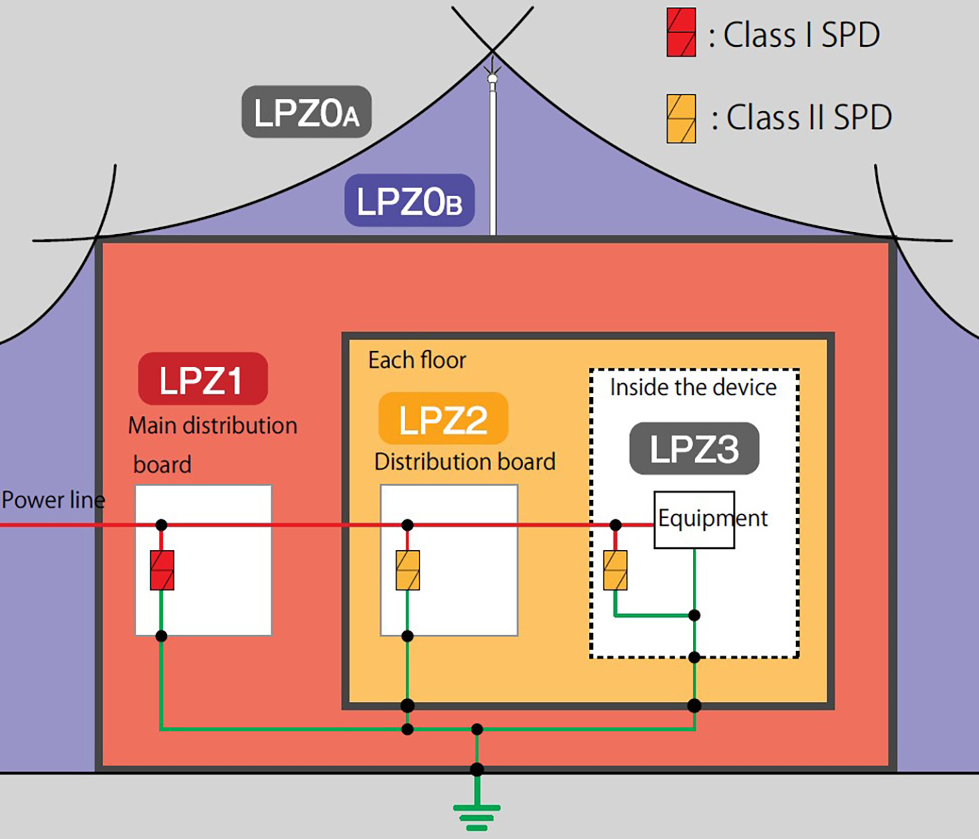
Lightning Protection Zone (LPZ) Overview
| Lightning protection zone | Overview | SPD class and category | |
|---|---|---|---|
| External | LPZ0A | Zone exposed to danger from direct lightning strike, total lightning current, and total lightning electromagnetic field. | SPD protection is recommended for outdoor facilities. |
| LPZ0B | Zone protected against direct lightning strikes, but exposed to partial lightning current and total lightning electromagnetic field. | ||
| Internal | LPZ1 | Zone protected against direct lightning strikes, but exposed to limited or induced lightning current and attenuated lightning electromagnetic fields. | Class I, Category D1 |
| LPZ2 | Zones protected against direct lightning strikes but exposed to induced current and lightning electromagnetic fields that are even more attenuated than LPZ1. | Class II, Category C2 | |
Grounding and bonding are key factors when applying equipotential bonding which is essentially the core of lightning protection. In order to achieve equipotential bonding with the entire building through grounding, it is desirable to use a structure-used grounding or grounding electrode system such as annular grounding electrode, mesh grounding electrode or foundation grounding electrode, and to have the grounding of each electrical equipment integrated.
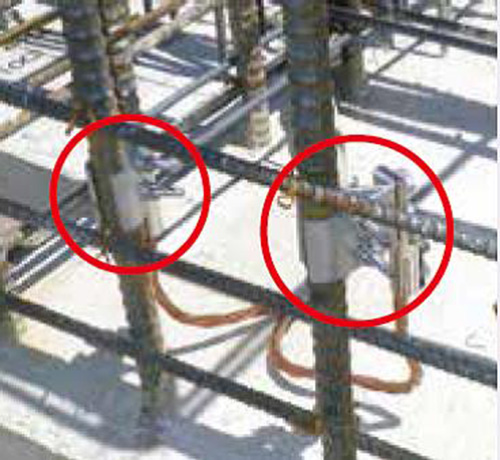
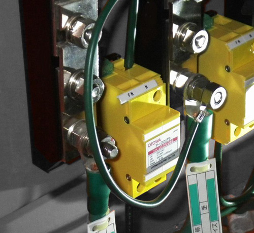
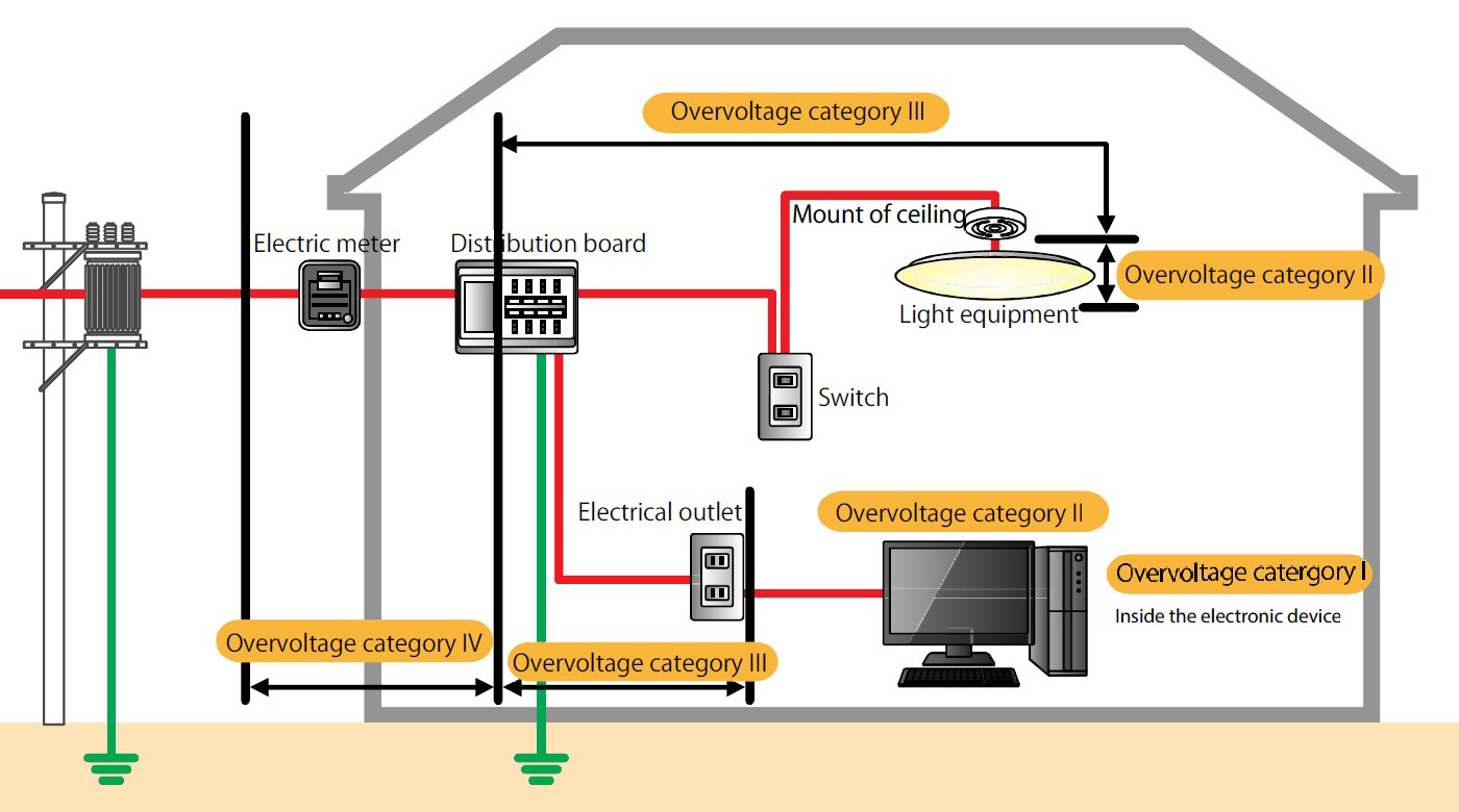
Table below shows how IEC60364-4-44 defines the impulse withstand voltage in the power supply system. The overvoltage category is classified into categories I to IV, and the equipment installed at each installation location must be selected such that their impulse withstand voltage is not smaller than the required specified impulse withstand voltage. From the figure of a house, it can be seen that the distribution board on each floor falls under impulse withstand voltage of category III, and the input section of electrical equipment falls under category II. Therefore, the voltage protection level of the SPD mounted on the Category III distribution board must be less than the Category II impulse withstand voltage.
It must be below, 1500V or less for the single-phase 3-wire system and 2500V or less for the three-phase 3-wire system.
| Nominal voltage of equipment | Required impulse withstand voltage | |||
|---|---|---|---|---|
| Equipment at the source of the facility (Overvoltage Category IV) |
Equipment for trunk and branch circuits (Overvoltage Category Ⅲ) |
Electrical appliances and equipment for electrical use (Overvoltage Category Ⅱ) |
Specially protected equipment (Overvoltage Category Ⅰ) |
|
| Single-phase 3- wire system 120-240V | 4000V | 2500V | 1500V | 800V |
| Three-phase 3- wire system 230/400V | 6000V | 4000V | 2500V | 1500V |
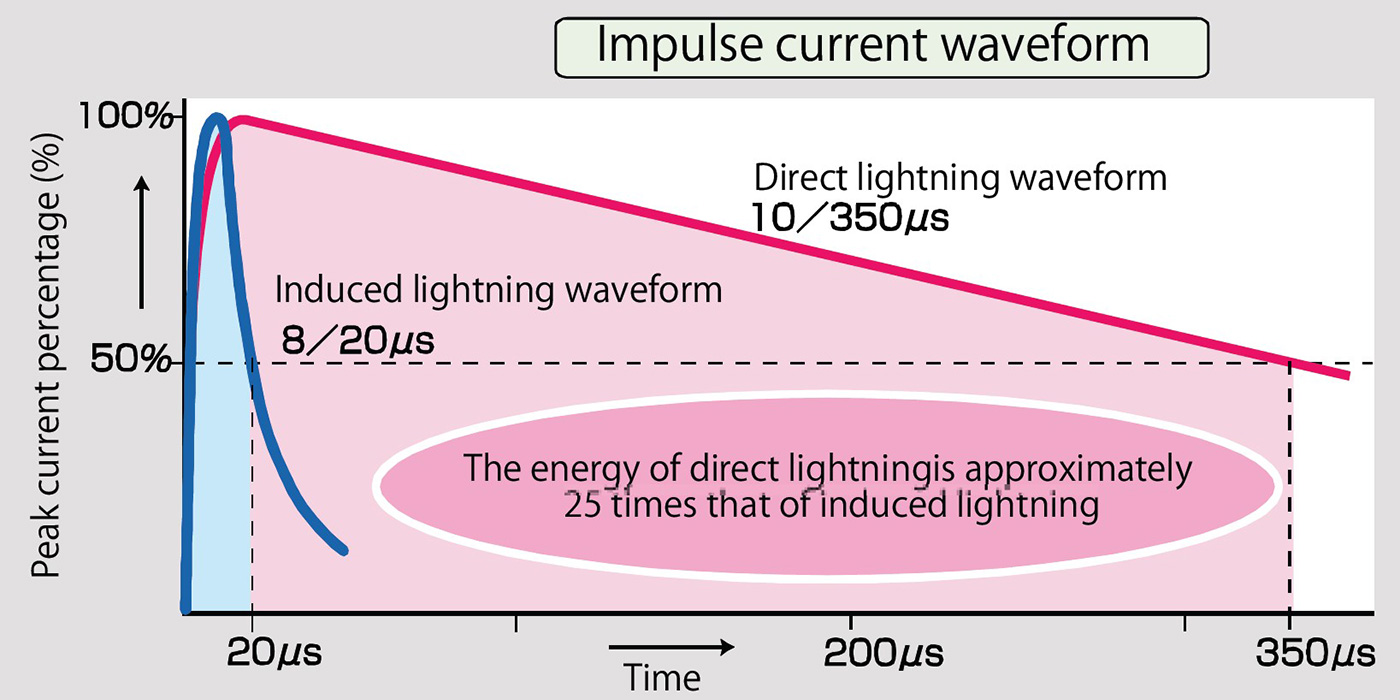
IEC stipulates that the current waveform of direct lightning is 10/350μs (representative waveform) and the current waveform of induced lightning is 8/20μs. Since the direct lightning waveform has a longer duration, the difference in energy (charge amount) from the induced lightning waveform is about 25 times or more energy when the current peak value is the same value.
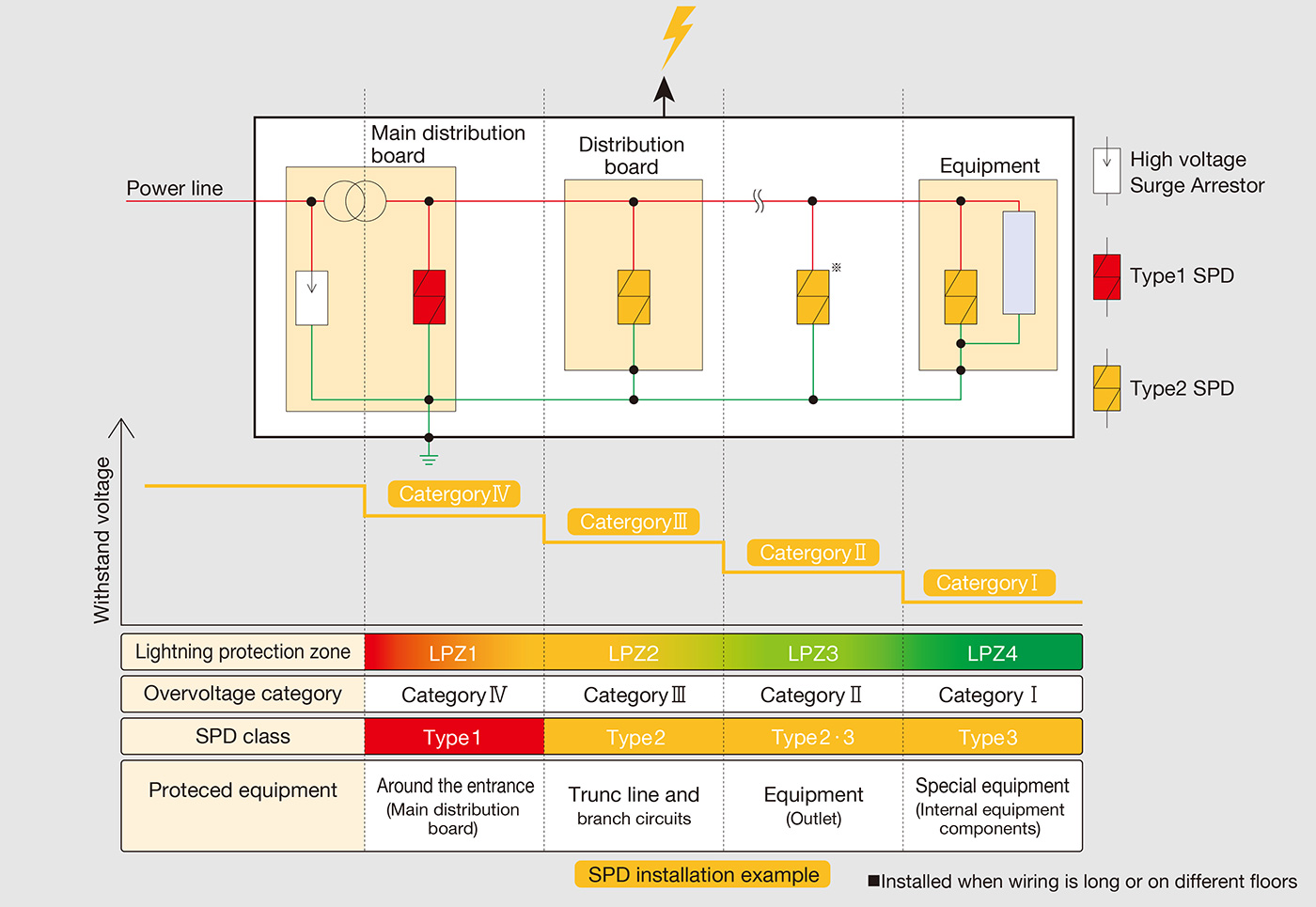
In order to avoid lightning damage in electrical equipment, it is important to prevent lightning surges from entering electrical equipment. As a countermeasure, insulation and magnetic shielding may be performed, but equipotential bonding by SPD (lightning arrester) is widely and generally implemented. Install SPDs at each lightning protection zone or overvoltage category boundary.
〇When examined by lightning protection zones, a portion of the direct lightning may divergence to LPZ1. Therefore, a class I or category D1 SPD for direct lightning will be installed at the boundary between LPZ0 and LPZ1. Since the effect of the lightning surge on LPZ2 to LPZ4 is attenuated compared to LPZ1, a class II / III or category C2 SPD for induced lightning will be installed at boundary between LPZ1 and LPZ2 or the boundary between LPZ2 and LPZ3.
〇When examined by overvoltage category, the voltage protection level of SPD installed in category III must be below the category II withstand voltage because the distribution board on each floor falls under overvoltage category III and the input of electrical equipment falls under category II.
IEC61643 series provide detailed information on how to test and handle SPDs. In actual design, it is necessary to select the optimal SPD after confirming “circuit voltage”, “system type” and “DC /AC” for power supply system, “operating voltage”, “frequency”, and “number of wires”, for communication and signal lines.
| Applications | IEC test standards | Installation location, purpose of installation, etc. | |
|---|---|---|---|
| For power supply | For direct lightning strikes |
|
Installed at power entrance, etc., to respond to direct lightning current flowing out of or into the building. |
| For induced lightning |
|
Installed in a distribution board, etc. inside a building to respond to induced lightning current that enters or occurs inside the building. | |
|
Installed near equipment inside a building to protect equipment from induced lightning current that enters or occurs inside the building. | ||
| For communication,signal | For direct lightning strikes |
|
Installed at signal line inlets, etc., to respond to direct lightning current flowing out of or into buildings. |
| For induced lightning |
|
Installed near equipment inside a building to protect equipment from induced lightning current that enters or occurs inside the building. | |