![]()
![]()
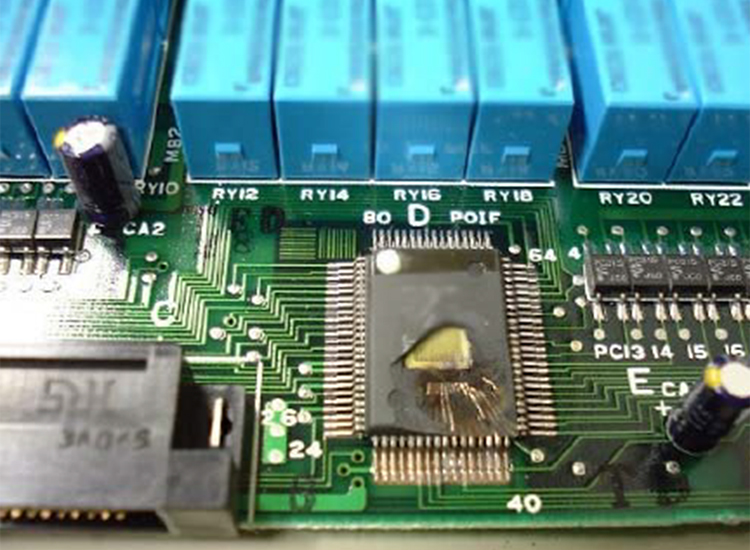
Failure of technical installations and systems in residential and functional buildings is very unpleasant and expensive. Therefore, faultless operation of devices must be ensured both during normal operation and thunder-storms. A professional solution allows to take adequate protection measures. The lightning protection zone concept, for example, enables designers, constructors and operators of buildings and installations to consider, implement and monitor different protection measures. All relevant devices, installations and systems are thus reliably protected at a reasonable expense.
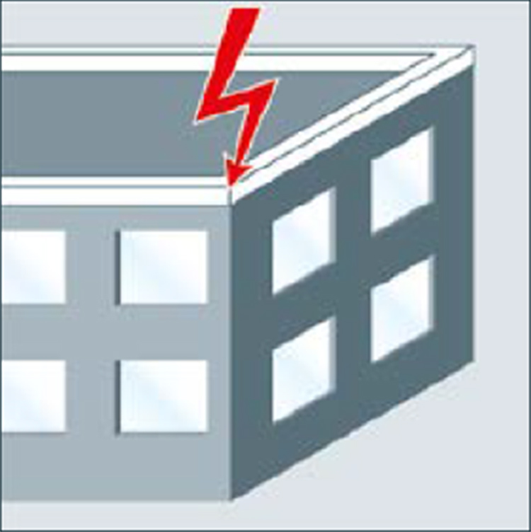
Surges occurring during a thunderstorm are caused by direct / near by lightning strikes or remote lightning strikes. Direct or near by lightning strikes are lightning strikes to a building, its surroundings or electrically conductive systems entering the building (e.g. low-voltage supply, telecommunication and data lines). The resulting impulse currents and impulse voltages as well as the associated Lightning Electromagnetic Pulse (LEMP) are particularly dangerous for the devices to be protected with regard to the amplitude and energy content involved. In case of a direct or nearby lightning strike, surges are caused by the voltage drop at the conventional earthing impedance R stand the resulting potential rise of the building in relation to the remote earth. This means the highest load for electrical installations in buildings. The characteristic parameters of the impulse current present (peak value, rate of current rise, charge, specific energy) can be described by means of the 10/350 μs impulse current wave form. They have been defined in international, European and national standards as test current for components and devices protecting against direct lightning strikes.
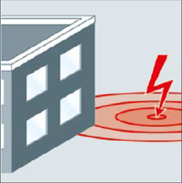
In addition to the voltage drop at the conventional earthing impedance, surges are generated in the electric building installation and the systems and devices connected to it due to the inductive effect of the electromagnetic lightning field. The energy of the induced surges and of the resulting impulse currents is far lower than the energy of a direct lightning impulse current and is therefore described by a 8/20 μs impulse current wave form. Components and devices that do not have to conduct currents resulting from direct lightning strikes are therefore tested with such 8/20 μs impulse currents.
The types of SPDs are categorized by testing currents having wave forms simulating the characteristics and energy size of the impulse currents.
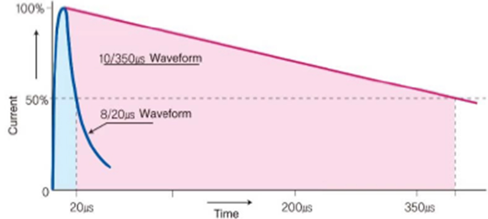
10/350μs wave form : The Lightning currents that can occur with a direct lightning strike can be simulated with the surge current of 10/350μs wave form. The Class1 SPD for protection of direct lightning surges and external lightning protection components are tested using this wave form.
8/20μs wave form : The surges created by remote lightning strikes and switching operations –indirect lightning surges - are simulated with the test impulse of 8/20μs wave form. The SPDs of Class2 and 3 are tested with this test impulse.
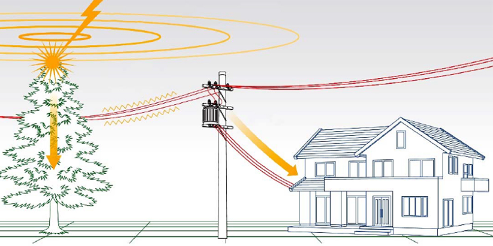
Lightning strikes are called remote if they occur at a farer distance to the object to be protected, strike medium-voltage overhead lines or their surroundings or occur as cloud-to-cloud lightning discharges. Similar to induced surges, the effects of remote lightning strikes on the electrical installation of a building are handled by device sand components which have been dimensioned according to 8/20 μs impulse current waves. Surges caused by switching operations (SEMP) are, for example, generated by:
The effects of switching operations in the electrical installation of a building can also be simulated by impulse currents of 8/20 μs wave form under test conditions. To ensure continuous availability of complex power supply and information technology systems even in case of direct lightning interference, further surge protection measures for electrical and electronic installations and devices based on a lightning protection system for the building are required. It is important to take all causes of surges into account. To do so, the lightning protection zone concept as described in IEC 62305-4 is applied.
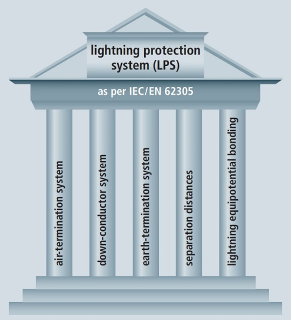
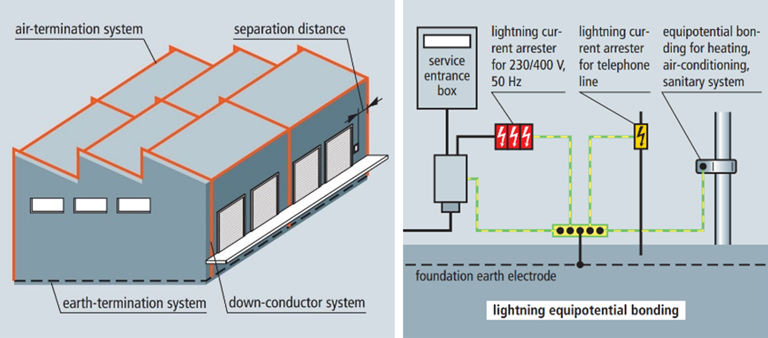
The function of a lightning protection system is to protect structures from fire or mechanical destruction and persons in the buildings from injury or even death. A lightning protection system consists of an external and an internal lightning protection system. (Figure4.1)
Lightning equipotential bonding reduces the potential differences caused by lightning currents. This is achieved by connecting all isolated conductive parts of the installation directly by means of conductors or surge protective devices (SPDs). (Figure4.2)
The four classes of LPS I, II, III and IV are determined using a set of construction rules including dimensioning requirements which are based on the relevant lightning protection level. Each set comprises class-dependent (e.g. radius of the rolling sphere, mesh size) and class-independent (e.g. cross-sections, materials) requirements.
To ensure permanent availability of complex information technology systems even in case of a direct lightning strike, additional measures, which supplement the lightning protection measures, are required to protect electronic systems against surges. These comprehensive measures are described in chapter 7 (lightning protection zone concept).
The building is divided into different endangered zones. These zones help to define the necessary protection measures, in particular the lightning and surge protection devices and components. Part of an EMC compatible(EMC: Electro Magnetic Compatibility) lightning protection zone conceptis the external lightning protection system (including air-termination system, down conductor system, earth-termination system), equipotential bonding, spatial shielding and surge protection for the power supply and information technology systems. Definitions apply as classified.
According to the requirements and loads placed on surge protective devices, they are categorized as lightning current arresters “Class Ⅰ ”, surge arresters “Class Ⅱ”. The highest requirements are placed on the discharge capacity of lightning current arresters “Class Ⅰ” used at the transition from lightning protection zone 0Ato 1 or0Ato 2.
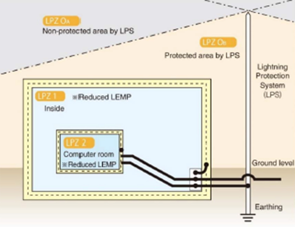
These arresters must be capable of conducting partial lightning currents of 10/350 μs wave form several times without being destroyed in order to prevent the ingress of destructive partial lightning current sin to the electrical installation of a building. At the transition point from LPZ 0B to 1 or downstream of the lightning current arrester “Class Ⅰ” at the transition point from LPZ 1 to 2 and higher, surge arresters “Class Ⅱ” are used to protect against surges. Their task is both to reduce the residual energy of the upstream protection stages even further and to limit the surges induced or generated in the installation itself.
The lightning and surge protective measures at the boundaries of the lightning protection zones described above equally apply to power supply and information technology systems. All measures described in the EMC compatible lightning protection zone concept help to achieve continuous availability of electrical and electronic devices and installations.
IEC 62305-4:2010
Outer zones:
LPZ 0
Zone where the threat is due to the unattenuated lightning electromagnetic field and where the internal systems may be subjected to full or partial lightning surge current.
LPZ 0 is subdivided into:
LPZ 0A
Zone where the threat is due to the direct lightning flash and the full lightning electromagnetic field. The internal systems may be subjected to full lightning surge current.
LPZ 0B
Zone protected against direct lightning flashes but where the threat is the full lightning electromagnetic field. The internal systems may be subjected to partial lightning surge currents.
Inner zones (protected against direct lightning flashes):
LPZ 1
Zone where the surge current is limited by current sharing and isolating interfaces and/or by SPD sat the boundary. Spatial shielding may attenuate the lightning electromagnetic field.
LPZ 2 ... n
Zone where the surge current may be further limited by current sharing and isolating interfaces and/or by additional SPD sat the boundary. Additional spatial shielding may be used to further attenuate the lightning electromagnetic field.
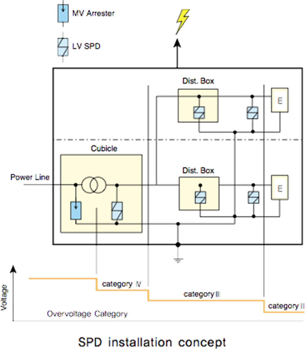
Impulse withstand category of electrical equipment
The IEC 60364-4-44 defines the basic impulse withstand voltage as described in the table below. The impulse withstand voltages of the categories shed light on the idea of the surge surpression level for the protected side by SPDs.
| Categories | UR | Examples | ||
|---|---|---|---|---|
| 230/400 V | 400/600 V | |||
| I | 1500 V | 2500 V | Equipment containing particularly sensitive electronic circuits: – computer workstations, computers, TV, HiFi, Video, Alarms, etc.; – Household appliances with electronic programmers, etc. |
|
| II | 2500 V | 4000 V | Domestic electrical equipment with mechanical progammers, portable tools, etc. | |
| III | 4000 V | 6000 V | Equipment subject to special requirements. Distribution panels, switches, breakers, etc. | |
| IV | 6000 V | 8000 V | Equipment for use at the origin of the installation. Electricity meters, circuit-breakers, etc. |
Protection level of SPD
In selection of SPD, the protection level (Up) shall be considered in accordance with the level of impulse withstand voltage to protect the equipment against transient surge.
Each equipment is rated with an impulse withstand voltage (Uw) depending on its category. An equipment can be operated without failure only if its withstand voltage is greater than the transient overvoltage between the live conductors and earth (common mode). If not, an SPD must be installed. Then the SPD protects the equipment from the transient voltages if the protection level (Up) of the SPD, which is defined as residual voltage level under the nominal current (In), is equal or lower than the impulse withstand voltage of the equipment :
Up ≤ Uw
Type and Classes of the Surge Protection Devices
Otowa power line SPDs are classified and tested in accordance with IEC 61643-11 and the relevant standards contain building regulations, requirements and tests for SPDs used in AC networks with nominal voltages of up to 1,000 V and nominal frequencies of 50 and 60 Hz.
This classification enables SPDs to cope with different requirements with regard to location, protection level and current carrying capacity. The Otowa surge protection devices can be installed in the energy supply network with full compliance with their respective functions.